


2004年
公司创立于
2008年
评为高新技术企业
2021年
首次进入规上企业
2022年
小巨人+单项冠军
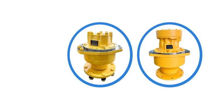
- New Products-
新品推荐

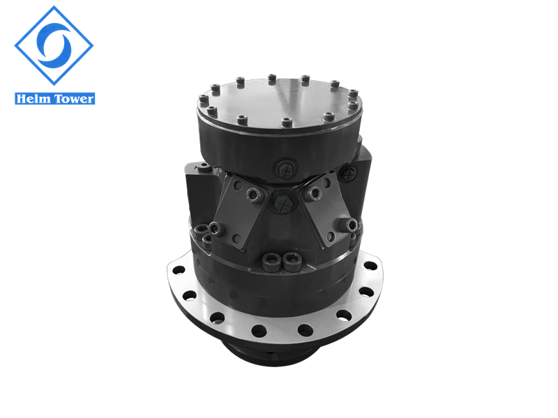
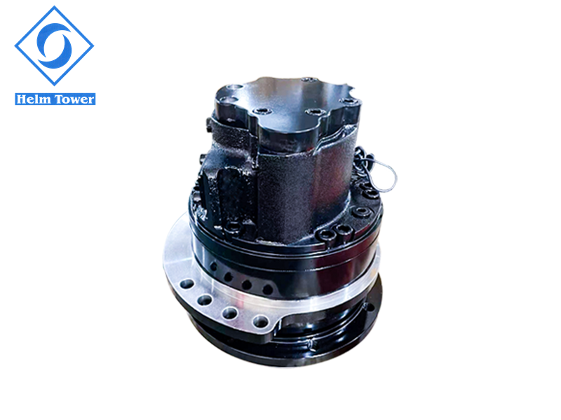
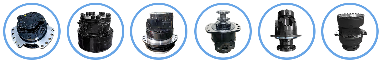
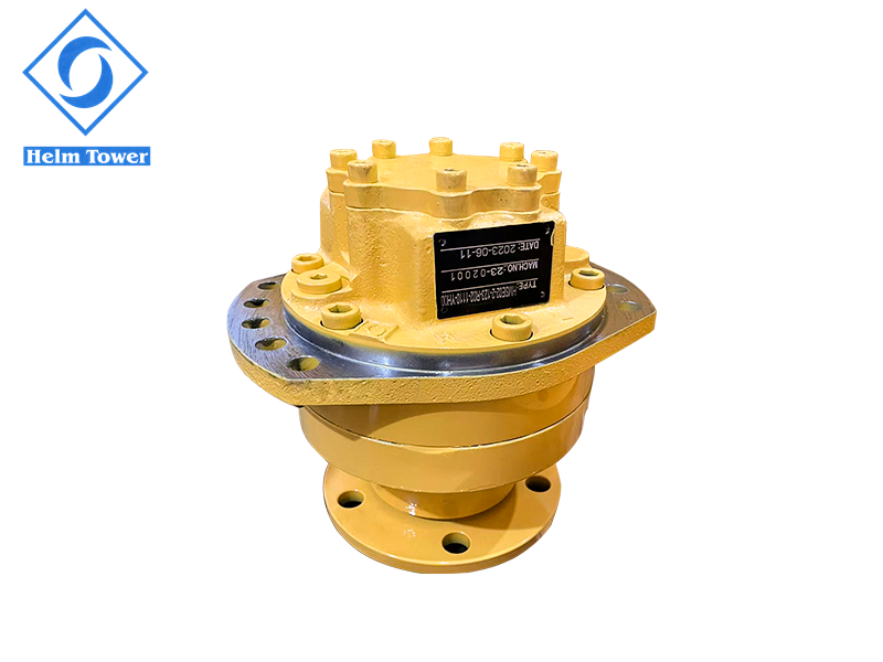
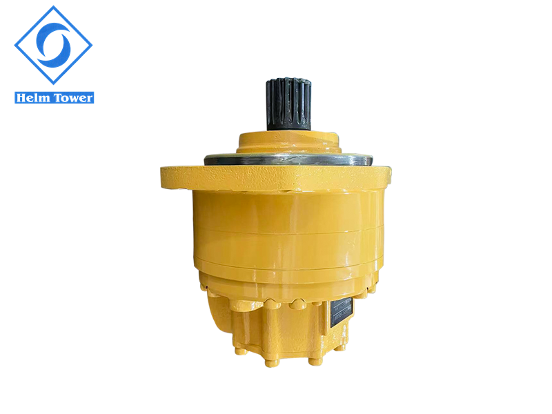
- Products show -
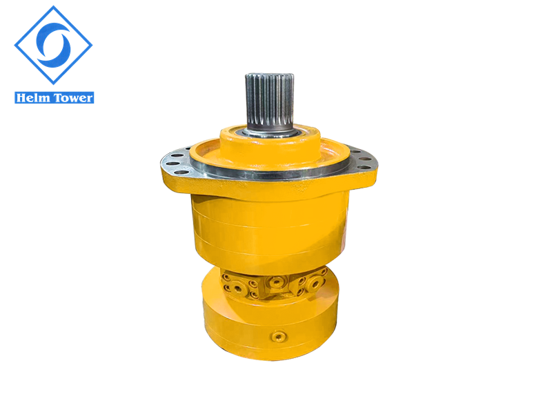
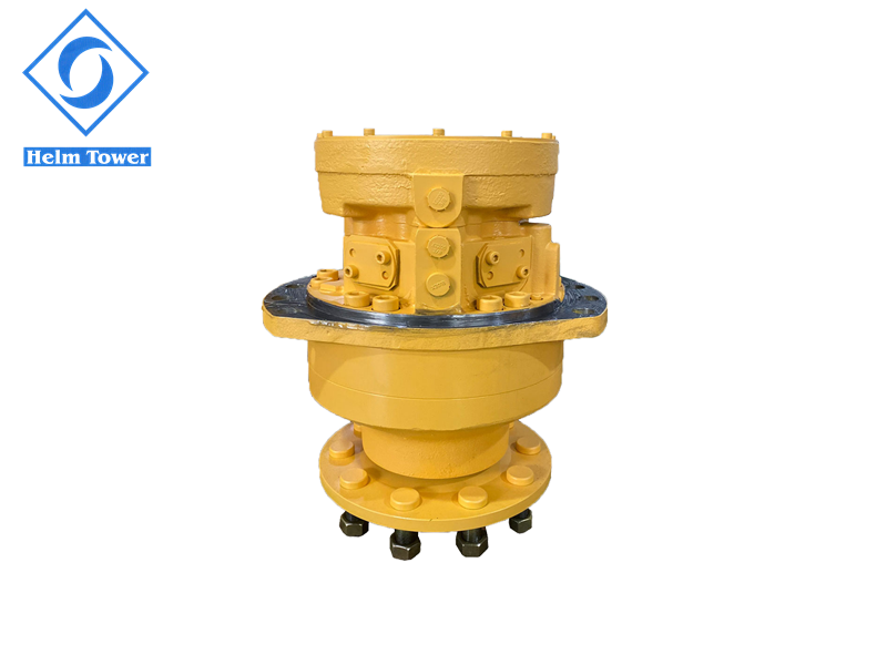
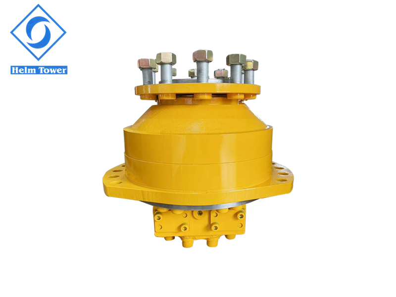
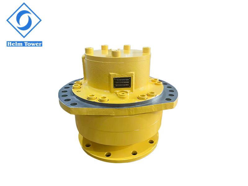
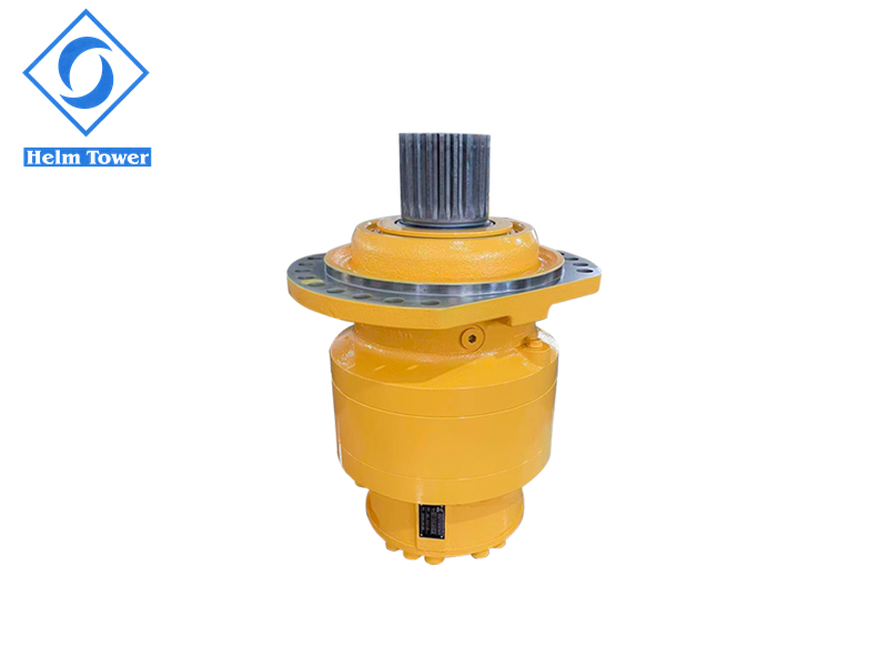
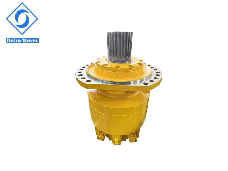
我们的主要产品
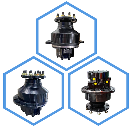
- Industry applications -
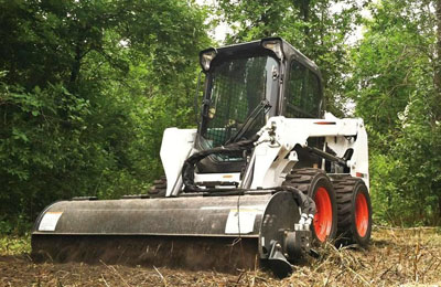
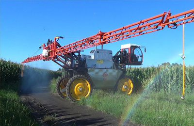
行业应用

- Latest News -
新闻中心

以匠心制造,打造液压传动新势力!
近日,恒通液压亮相亚洲动力传动与控制技术展览会(PTC ASIA),以“精控动力·驱动未来”为主题,打造了科技感十足的沉浸式展台,向全球客户展示了科技感十足的新
详细介绍 →


-- About us
关于我们
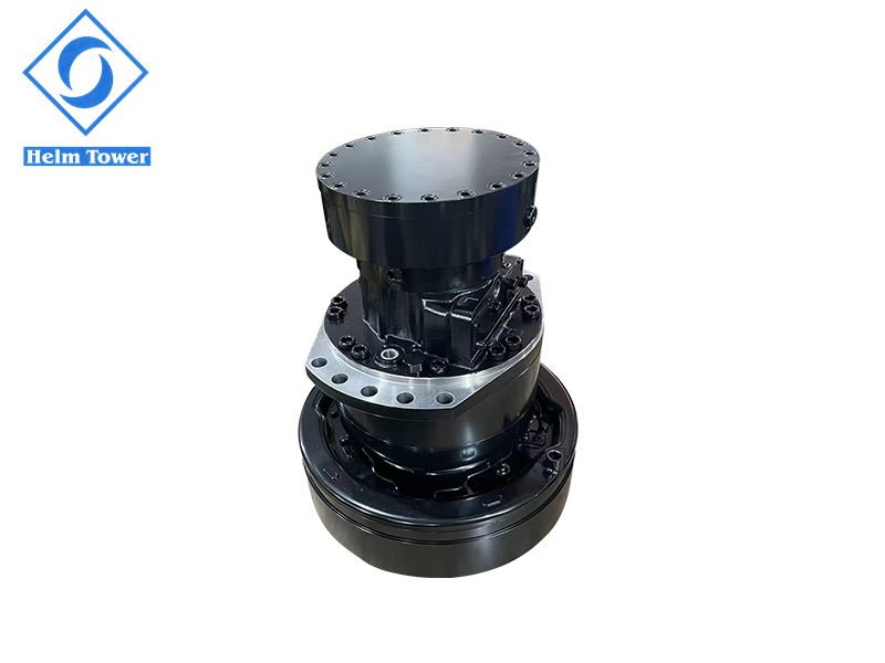
恒通液压成立于2004年,是一家专业研发、生产、销售低速大扭矩径向柱塞马达、铣挖机的国家高新技术企业。恒通液压坐落于浙江省宁波市镇海区,占地面积二十多亩,年产值8000多万元。
本着“专注、专业、创新”的精神,恒通液压长期致力于低速大扭矩径向柱塞液压马达的研发,公司拥有一支高素质的技术研发团队,他们由几十位液压行业的资深工程师组成。......

科技创新
以研究掌握液压关键技术为核心。形成高性能液压马达、液压系统组件、液压行走机械的金字塔型产品结构。

应用广泛
产品广泛用于船舶、煤矿机械、农业机械、工程机械、森林机械以及路面机械等众多领域。